Robotics and motor control
Drives up to 253 SC/ST serial bus servos (ST3215, STS3215) over half-duplex UART1 on GPIO18/19, with angle, load and voltage read-back.
Engineering inference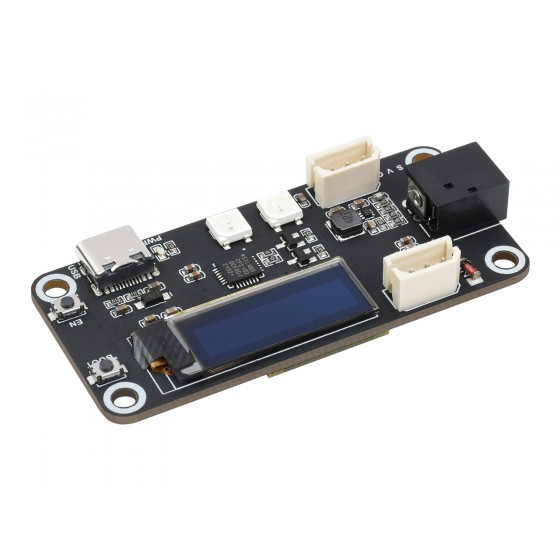
Waveshare
Waveshare Servo Driver with ESP32 (SKU 21593) is a 65 × 30 mm ESP32-WROOM-32 board that drives up to 253 SC/ST serial bus servos (ST3215, STS3215) from two 3-pin S/V/G headers: half-duplex UART1 on GPIO19 (TX) / GPIO18 (RX), 6–12 V DC jack passed straight to the servos, 0.91″ OLED on I2C GPIO21/22, two WS2812 LEDs on GPIO23, CP2102 USB-C, about $16.
Servo Driver with ESP32Development boardFacts about the complete product. Unknown values remain open design questions.
Guidance to help you shortlist. The basis is shown for each recommendation.
Drives up to 253 SC/ST serial bus servos (ST3215, STS3215) over half-duplex UART1 on GPIO18/19, with angle, load and voltage read-back.
Engineering inferenceMain controller for bus-servo robot arms, hands, hexapods and humanoids; two S/V/G servo ports fed straight from the 6–12 V jack.
Engineering inferenceESP32 Wi-Fi, Bluetooth and ESP-NOW for remote servo control from the open-source web app.
Engineering inferenceThe board is the parent product. Each chip has its own memory, pins, capabilities and thermal limits.
Espressif Systems
e517763a-027e-5237-9c11-e82015f99135--moduleEspressif Systems
e517763a-027e-5237-9c11-e82015f99135--mcuSilicon Labs
e517763a-027e-5237-9c11-e82015f99135--u2Advanced Monolithic Systems
e517763a-027e-5237-9c11-e82015f99135--u3Texas Instruments
e517763a-027e-5237-9c11-e82015f99135--u4Texas Instruments
e517763a-027e-5237-9c11-e82015f99135--u5Solomon Systech (controller)
e517763a-027e-5237-9c11-e82015f99135--u6Generated from the datasheet's dimensioned drawing and measured against it. Download the STEP to check fit in your own enclosure.
thickness=1.6 mm assumed: PCB thickness not printed; 1.6 mm assumed for the CAD envelope only
20 board pins and 9 explicit routes documented. The record marks the pinout complete. Alternate functions can share pins and may not be usable together.
Board connector positions are the physical points you wire to.
| Board pin | Connector / position | Electrical | Functions / constraints |
|---|---|---|---|
| VIN 6-12VID CN1-VCC | CN1Position unknown | power in | power_in DC-044 5.5×2.1 mm barrel jack, 6–12 V; input voltage must match the servos |
| GNDID CN1-GND | CN1Position unknown | 0 Vground | ground |
| SID H2-1 | H2Position 1 | signal | s serial bus servo DATA (half-duplex UART1 via SN74LVC1G125/126 buffers) |
| VID H2-2 | H2Position 2 | power out | power_out servo supply = DC jack input 6–12 V (not regulated) |
| GID H2-3 | H2Position 3 | 0 Vground | ground |
| SID H3-1 | H3Position 1 | signal | s serial bus servo DATA (same net as H2-1) |
| VID H3-2 | H3Position 2 | power out | power_out servo supply = DC jack input 6–12 V |
| GID H3-3 | H3Position 3 | 0 Vground | ground |
| 5VID H1-1 | H1Position 1 | power out | power_out RGB-LED extension interface (XH1.25), 5 V rail |
| GNDID H1-2 | H1Position 2 | 0 Vground | ground |
| OUTID H1-3 | H1Position 3 | signal | out LED-OUT: data out of the second on-board WS2812B, chains external WS2812 LEDs |
| ENID M1-3 | M1Position 3 | control5 V tolerant: no | en reset: EN button S2 (10K pull-up R4, 104 cap C1) and auto-program transistor VT1 (CP2102 DTR/RTS) |
| IO0ID M1-25 | M1Position 25 | 3.3 Vgpio5 V tolerant: noMax drive 28 mA | GPIO0, ADC2_CH1, RTC_GPIO11, TOUCH1, EMAC_TX_CLK, CLK_OUT1, GPIO matrix (UART/I2C/I2S/SPI/LEDC PWM/MCPWM/RMT/PCNT/TWAI routable)Boot strapping pin BOOT button S1 (KEY_FLASH, 10K pull-up R5) and auto-program transistor VT2; strapping pin |
| U0TXDID M1-35 | M1Position 35 | 3.3 Vgpio5 V tolerant: noMax drive 28 mA | GPIO1, U0TXD, CLK_OUT3, EMAC_RXD2, GPIO matrix (UART/I2C/I2S/SPI/LEDC PWM/MCPWM/RMT/PCNT/TWAI routable) UART0 TX → CP2102 RXD via 100R (R2); USB-C serial / programming |
| U0RXDID M1-34 | M1Position 34 | 3.3 Vgpio5 V tolerant: noMax drive 28 mA | GPIO3, U0RXD, CLK_OUT2, GPIO matrix (UART/I2C/I2S/SPI/LEDC PWM/MCPWM/RMT/PCNT/TWAI routable) UART0 RX ← CP2102 TXD via 100R (R1) |
| IO19ID M1-31 | M1Position 31 | 3.3 Vgpio5 V tolerant: noMax drive 28 mA | GPIO19, U0CTS, VSPIQ, EMAC_TXD0, GPIO matrix (UART/I2C/I2S/SPI/LEDC PWM/MCPWM/RMT/PCNT/TWAI routable) U1TXD: servo bus transmit through SN74LVC1G126 (U3), enabled by PNP Q1 (TXEN) |
| IO18ID M1-30 | M1Position 30 | 3.3 Vgpio5 V tolerant: noMax drive 28 mA | GPIO18, HS1_DATA7, VSPICLK, GPIO matrix (UART/I2C/I2S/SPI/LEDC PWM/MCPWM/RMT/PCNT/TWAI routable) U1RXD: servo bus receive through SN74LVC1G125 (U4) |
| IO21ID M1-33 | M1Position 33 | 3.3 Vgpio5 V tolerant: noMax drive 28 mA | GPIO21, VSPIHD, EMAC_TX_EN, GPIO matrix (UART/I2C/I2S/SPI/LEDC PWM/MCPWM/RMT/PCNT/TWAI routable) I2C SDA → 0.91″ 128×32 SSD1306 OLED (4.7K pull-up R17) |
| IO22ID M1-36 | M1Position 36 | 3.3 Vgpio5 V tolerant: noMax drive 28 mA | GPIO22, U0RTS, VSPIWP, EMAC_TXD1, GPIO matrix (UART/I2C/I2S/SPI/LEDC PWM/MCPWM/RMT/PCNT/TWAI routable) I2C SCL → SSD1306 OLED (4.7K pull-up R16) |
| IO23ID M1-37 | M1Position 37 | 3.3 Vgpio5 V tolerant: noMax drive 28 mA | GPIO23, HS1_STROBE, VSPID, GPIO matrix (UART/I2C/I2S/SPI/LEDC PWM/MCPWM/RMT/PCNT/TWAI routable) WS2812B data in (L1 → L2 → H1 LED-OUT) |
A board label, a chip signal ID and a package lead number are different identifiers.
| Board connection | Chip instance | Chip signal | Package lead | Route |
|---|---|---|---|---|
M1-3 | ESP32-D0WD-VInstance e517763a-027e-5237-9c11-e82015f99135--mcu | CHIP_PUID CHIP_PU | — | direct |
M1-25 | ESP32-D0WD-VInstance e517763a-027e-5237-9c11-e82015f99135--mcu | GPIO0ID GPIO0 | — | direct |
M1-35 | ESP32-D0WD-VInstance e517763a-027e-5237-9c11-e82015f99135--mcu | GPIO1ID GPIO1 | — | direct |
M1-34 | ESP32-D0WD-VInstance e517763a-027e-5237-9c11-e82015f99135--mcu | GPIO3ID GPIO3 | — | direct |
M1-31 | ESP32-D0WD-VInstance e517763a-027e-5237-9c11-e82015f99135--mcu | GPIO19ID GPIO19 | — | direct |
M1-30 | ESP32-D0WD-VInstance e517763a-027e-5237-9c11-e82015f99135--mcu | GPIO18ID GPIO18 | — | direct |
M1-33 | ESP32-D0WD-VInstance e517763a-027e-5237-9c11-e82015f99135--mcu | GPIO21ID GPIO21 | — | direct |
M1-36 | ESP32-D0WD-VInstance e517763a-027e-5237-9c11-e82015f99135--mcu | GPIO22ID GPIO22 | — | direct |
M1-37 | ESP32-D0WD-VInstance e517763a-027e-5237-9c11-e82015f99135--mcu | GPIO23ID GPIO23 | — | direct |
Chip signals stay attached to their chip instance, including their package lead and board exposure.
Chip package pins have not been transcribed for this instance.
Chip signals stay attached to their chip instance, including their package lead and board exposure.
Chip package pins have not been transcribed for this instance.
Chip signals stay attached to their chip instance, including their package lead and board exposure.
Chip package pins have not been transcribed for this instance.
Chip signals stay attached to their chip instance, including their package lead and board exposure.
Chip package pins have not been transcribed for this instance.
Chip signals stay attached to their chip instance, including their package lead and board exposure.
Chip package pins have not been transcribed for this instance.
Chip signals stay attached to their chip instance, including their package lead and board exposure.
Chip package pins have not been transcribed for this instance.
Chip signals stay attached to their chip instance, including their package lead and board exposure.
Chip package pins have not been transcribed for this instance.
Supply voltage and GPIO logic voltage describe different parts of the design.
| Input | Voltage range | Connector | Notes |
|---|---|---|---|
| VIN 6-12V | 6 to 12 V | — | DC-044 5.5×2.1 mm barrel jack, 6–12 V; input voltage must match the servos |
A 5 V supply input does not establish 5 V tolerance on GPIO. Check the documented power input and logic domain for each connection.
These describe the assembled board. Interface counts do not guarantee simultaneous operation.
| Interface | Support | Count | Details |
|---|---|---|---|
| gpio | Documented | Unknown | M1-25, M1-35, M1-34, M1-31, M1-30, M1-33, M1-36, M1-37 |
| adc | Documented | Unknown | M1-25 |
| rtc_gpio | Documented | Unknown | M1-25 |
| touch | Documented | Unknown | M1-25 |
| ethernet | Documented | Unknown | M1-25, M1-35, M1-31, M1-33, M1-36 |
| clock | Documented | Unknown | M1-25, M1-35, M1-34 |
| gpio_matrix | Documented | Unknown | M1-25, M1-35, M1-34, M1-31, M1-30, M1-33, M1-36, M1-37 |
| uart | Documented | Unknown | M1-35, M1-34, M1-31, M1-36 |
| spi | Documented | Unknown | M1-31, M1-30, M1-33, M1-36, M1-37 |
| sdio | Documented | Unknown | M1-30, M1-37 |
| usb | Documented | 1 | USB Type-C via CP2102 USB-UART bridge |
Board capacity includes installed memory; chip-local memory is listed separately under each processor.
Capacities use KiB / MiB (1024-based units). Firmware partitions and runtime allocations reduce application-available memory.
Product operating conditions, chip ambient ratings, package case limits and junction maxima remain separate.
Reported product dimensions may exclude protruding components. Unknown height does not establish a complete clearance envelope.
Attached generated geometry is an approximate envelope. A generated outline does not establish an electrically verified PCB footprint.
| ID / type | Pins | Pitch | Notes |
|---|---|---|---|
| CN1DC barrel jack 5.5 × 2.1 mm, 6–12 V | 2 | Unknown | — |
| H2serial bus servo port, 3-pin S/V/G (DATA, 6–12 V, GND) | 3 | Unknown | — |
| H3serial bus servo port, 3-pin S/V/G (DATA, 6–12 V, GND) | 3 | Unknown | — |
| H1RGB-LED extension interface, XH1.25 3-pin (5V, GND, OUT) | 3 | Unknown | — |
| usbUSB Type-C (CP2102 USB-UART, programming + power) | Unknown | Unknown | — |
Every available field, including details beyond the summaries. Null means the value has not been established.
US / USD is the target market. Observed price and stock are separate from a delivery quote.
US · USD
This observation is stale or has no verified check time. Recheck with the supplier.
Visit supplier (opens in a new tab)Delivery depends on quantity, postal code and shipping method. A dispatch statement such as “ship today” is not an arrival estimate.
Each source keeps its own verification status. Confirm the part revision and file contents before using it in a design.
Manufacturer reference
Manufacturer reference
inspected: black PCB with 0.91 in blue OLED, USB-C with EN/BOOT buttons, two RGB LEDs, CP2102 QFN, two white 3-pin servo ports and a 5.5 mm DC jack, four corner holes; maker store photo
Generated asset
cad_check passed
Generated envelope geometry may also exist for this record. It does not replace manufacturer CAD or a verified electrical land pattern.
Document provenance, retrieval dates and the field groups supported by each source.
Supports: spec.constraints.electrical.io_voltage_v, spec.constraints.electrical.logic_high_min_v, spec.constraints.electrical.pin_drive_max_ma, spec.constraints.electrical.supply_voltage_max_v, spec.constraints.electrical.supply_voltage_min_v, spec.geometry.cad.assumptions, spec.geometry.cad.bbox.height_mm, spec.geometry.cad.bbox.length_mm, spec.geometry.cad.bbox.width_mm, spec.geometry.cad.envelope_complete, spec.geometry.cad.mesh_path, spec.geometry.cad.step_path, spec.geometry.cad.verification, spec.geometry.dimensions.length_mm, spec.geometry.dimensions.width_mm, spec.geometry.mounting_holes, spec.provides.capabilities, spec.provides.features, spec.provides.memory.sram_kb, spec.provides.software_frameworks, spec.provides.wireless, spec.usage.connectors, spec.usage.pin_mappings, spec.usage.pinout, spec.usage.pinout_complete, spec.usage.requirements.power_inputs
sha256 88e1643f0d5828614b0771e084de4a035205456d1714e93dca03c32e99b2756a
Supports: offers
The Waveshare Servo Driver with ESP32 is built around the ESP32-D0WD-V, alongside ESP32-WROOM-32, CP2102, AMS1117-3.3, SN74LVC1G126DBV.
No. The I/O pins are not 5 V tolerant — they run at 3.3 V logic; use a level shifter for 5 V signals. Input-high threshold: 2.475–3.6 V.
Documented output-high current per pin: 40 mA typ. Values are traced to the chip datasheet; see the pinout table for per-pin limits and conditions.
Supply range 6–12 V. Power inputs: VIN 6-12V (6–12 V).
From $15.99 at www.waveshare.com. Prices are observed unit prices before tax and shipping.
65 × 30 mm. A STEP model is available for enclosure fit checks.
gpio, adc, rtc_gpio, touch, ethernet, clock, gpio_matrix, uart, spi, sdio, usb.
Supported frameworks: Arduino IDE.
Every value in this record is traced to a source — 2 documents including the board and chip datasheets — with the page and table cited per value. Unknowns are left explicit, never guessed.