Connected IoT devices and wireless sensor nodes
On-board radio: IEEE 802.15.4 (Zigbee 3.0 / Thread); Bluetooth 5.3 LE.
Engineering inference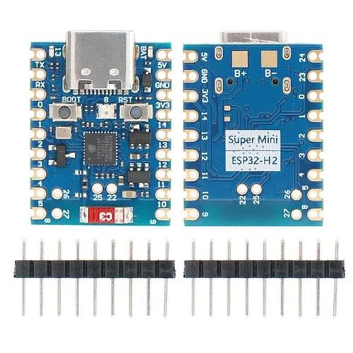
Generic (unbranded)
The ESP32-H2 SuperMini is a stamp-size generic board on the ESP32-H2FH4S: 96 MHz RISC-V, 4 MB flash, 320 KB SRAM, Bluetooth 5.3 LE and 802.15.4 for Zigbee 3.0 / Thread / Matter, and no Wi-Fi. USB-C goes to native USB Serial/JTAG. It breaks out 19 GPIO (5 ADC), has BOOT / RESET, a WS2812 on GPIO8, a blue LED on GPIO13, BAT pads and 3.3 V logic, 24 × 18.4 mm, $6.95.
ESP32-H2 SuperMiniDevelopment boardFacts about the complete product. Unknown values remain open design questions.
Guidance to help you shortlist. The basis is shown for each recommendation.
On-board radio: IEEE 802.15.4 (Zigbee 3.0 / Thread); Bluetooth 5.3 LE.
Engineering inference24.0 × 18.4 mm footprint.
Engineering inferencePrograms from Arduino IDE, ESP-IDF, ESPHome.
Engineering inferenceThe board is the parent product. Each chip has its own memory, pins, capabilities and thermal limits.
Espressif Systems
ea0055c1-998a-5ef4-922b-285491fd2839--mcuGenerated from the datasheet's dimensioned drawing and measured against it. Download the STEP to check fit in your own enclosure.
thickness=1.6 mm assumed: PCB thickness not printed; 1.6 mm assumed for the CAD envelope only
22 board pins and 19 explicit routes documented. The record marks the pinout complete. Alternate functions can share pins and may not be usable together.
Board connector positions are the physical points you wire to.
| Board pin | Connector / position | Electrical | Functions / constraints |
|---|---|---|---|
| 5VID 5V | —Position R1 | 5 Vpower in | power_in 5V power input for the board |
| GNDID GND | —Position R2 | 0 Vground | ground Ground connection |
| 3V3ID 3V3 | —Position R3 | power out | power_out 3.3V power output for peripherals |
| 0ID 0 | —Position L3 | 3.3 Vgpio5 V tolerant: noMax drive 28 mA | GPIO0, FSPIQ GPIO |
| 1ID 1 | —Position L4 | 3.3 Vgpio5 V tolerant: noMax drive 28 mA | ADC1_CH0, GPIO1, FSPICS0 GPIO, ADC pin |
| 2ID 2 | —Position L5 | 3.3 Vgpio5 V tolerant: noMax drive 28 mA | ADC1_CH1, GPIO2, MTMS, FSPIWP GPIO, ADC pin |
| 3ID 3 | —Position L6 | 3.3 Vgpio5 V tolerant: noMax drive 28 mA | ADC1_CH2, GPIO3, MTDO, FSPIHD GPIO, ADC pin |
| 4ID 4 | —Position L7 | 3.3 Vgpio5 V tolerant: noMax drive 28 mA | ADC1_CH3, GPIO4, MTCK, FSPICLK GPIO, ADC pin |
| 5ID 5 | —Position L8 | 3.3 Vgpio5 V tolerant: noMax drive 28 mA | ADC1_CH4, GPIO5, MTDI, FSPID GPIO, ADC pin |
| 8ID 8 | —Position L9 | 3.3 Vgpio5 V tolerant: noMax drive 28 mA | onboard WS2812 RGB LED, strapping (boot mode / ROM log), floating by default, GPIO8 GPIO, LOG |
| 9ID 9 | —Position R9 | 3.3 Vgpio5 V tolerant: noMax drive 28 mA | BOOT button (low at reset = download mode), strapping (boot mode), weak pull-up, GPIO9 GPIO, BOOT |
| 10ID 10 | —Position R8 | 3.3 Vgpio5 V tolerant: noMax drive 28 mA | ZCD0 (zero-cross detect), GPIO10 GPIO |
| 11ID 11 | —Position R7 | 3.3 Vgpio5 V tolerant: noMax drive 28 mA | ZCD1 (zero-cross detect), GPIO11 GPIO |
| 12ID 12 | —Position R6 | 3.3 Vgpio5 V tolerant: noMax drive 28 mA | GPIO12 GPIO |
| 13ID 13 | —Position R5 | 3.3 Vgpio5 V tolerant: noMax drive 28 mA | blue user LED, XTAL_32K_P, GPIO13 GPIO, LED |
| 14ID 14 | —Position R4 | 3.3 Vgpio5 V tolerant: noMax drive 28 mA | XTAL_32K_N, GPIO14 GPIO |
| 22ID 22 | —Position inner pad | 3.3 Vgpio5 V tolerant: noMax drive 28 mA | GPIO22 GPIO |
| 24ID 24 | —Position L1 | 3.3 Vgpio5 V tolerant: noMax drive 28 mA | TX (UART0), GPIO24, U0TXD, FSPICS2 TX |
| 23ID 23 | —Position L2 | 3.3 Vgpio5 V tolerant: noMax drive 28 mA | RX (UART0), GPIO23, U0RXD, FSPICS1 GPIO |
| 25ID 25 | —Position inner pad | 3.3 Vgpio5 V tolerant: noMax drive 28 mA | strapping (JTAG source), floating by default, GPIO25, FSPICS3 GPIO |
| 26ID 26 | —Position inner pad | 3.3 Vgpio5 V tolerant: noMax drive 28 mA | USB_D-, GPIO26, FSPICS4 GPIO |
| 27ID 27 | —Position inner pad | 3.3 Vgpio5 V tolerant: noMax drive 28 mA | USB_D+, GPIO27, FSPICS5 GPIO |
A board label, a chip signal ID and a package lead number are different identifiers.
| Board connection | Chip instance | Chip signal | Package lead | Route |
|---|---|---|---|---|
0 | ESP32-H2FH4SInstance ea0055c1-998a-5ef4-922b-285491fd2839--mcu | GPIO0ID GPIO0 | — | direct |
1 | ESP32-H2FH4SInstance ea0055c1-998a-5ef4-922b-285491fd2839--mcu | GPIO1ID GPIO1 | — | direct |
2 | ESP32-H2FH4SInstance ea0055c1-998a-5ef4-922b-285491fd2839--mcu | GPIO2ID GPIO2 | — | direct |
3 | ESP32-H2FH4SInstance ea0055c1-998a-5ef4-922b-285491fd2839--mcu | GPIO3ID GPIO3 | — | direct |
4 | ESP32-H2FH4SInstance ea0055c1-998a-5ef4-922b-285491fd2839--mcu | GPIO4ID GPIO4 | — | direct |
5 | ESP32-H2FH4SInstance ea0055c1-998a-5ef4-922b-285491fd2839--mcu | GPIO5ID GPIO5 | — | direct |
8 | ESP32-H2FH4SInstance ea0055c1-998a-5ef4-922b-285491fd2839--mcu | GPIO8ID GPIO8 | — | direct |
9 | ESP32-H2FH4SInstance ea0055c1-998a-5ef4-922b-285491fd2839--mcu | GPIO9ID GPIO9 | — | direct |
10 | ESP32-H2FH4SInstance ea0055c1-998a-5ef4-922b-285491fd2839--mcu | GPIO10ID GPIO10 | — | direct |
11 | ESP32-H2FH4SInstance ea0055c1-998a-5ef4-922b-285491fd2839--mcu | GPIO11ID GPIO11 | — | direct |
12 | ESP32-H2FH4SInstance ea0055c1-998a-5ef4-922b-285491fd2839--mcu | GPIO12ID GPIO12 | — | direct |
13 | ESP32-H2FH4SInstance ea0055c1-998a-5ef4-922b-285491fd2839--mcu | GPIO13ID GPIO13 | — | direct |
14 | ESP32-H2FH4SInstance ea0055c1-998a-5ef4-922b-285491fd2839--mcu | GPIO14ID GPIO14 | — | direct |
22 | ESP32-H2FH4SInstance ea0055c1-998a-5ef4-922b-285491fd2839--mcu | GPIO22ID GPIO22 | — | direct |
24 | ESP32-H2FH4SInstance ea0055c1-998a-5ef4-922b-285491fd2839--mcu | GPIO24ID GPIO24 | — | direct |
23 | ESP32-H2FH4SInstance ea0055c1-998a-5ef4-922b-285491fd2839--mcu | GPIO23ID GPIO23 | — | direct |
25 | ESP32-H2FH4SInstance ea0055c1-998a-5ef4-922b-285491fd2839--mcu | GPIO25ID GPIO25 | — | direct |
26 | ESP32-H2FH4SInstance ea0055c1-998a-5ef4-922b-285491fd2839--mcu | GPIO26ID GPIO26 | — | direct |
27 | ESP32-H2FH4SInstance ea0055c1-998a-5ef4-922b-285491fd2839--mcu | GPIO27ID GPIO27 | — | direct |
Chip signals stay attached to their chip instance, including their package lead and board exposure.
Chip package pins have not been transcribed for this instance.
Supply voltage and GPIO logic voltage describe different parts of the design.
| Input | Voltage range | Connector | Notes |
|---|---|---|---|
| 5V | Unknown | — | 5V power input for the board |
A 5 V supply input does not establish 5 V tolerance on GPIO. Check the documented power input and logic domain for each connection.
These describe the assembled board. Interface counts do not guarantee simultaneous operation.
| Interface | Support | Count | Details |
|---|---|---|---|
| gpio | Documented | Unknown | 0, 1, 2, 3, 4, 5, 8, 9, 10, 11, 12, 13, 14, 22, 24, 23, 25, 26, 27 |
| spi | Documented | Unknown | 0, 1, 2, 3, 4, 5, 24, 23, 25, 26, 27 |
| adc | Documented | 5 | 1, 2, 3, 4, 5count stated in datasheet (adc_channels) |
| jtag | Documented | Unknown | 2, 3, 4, 5 |
| led | Documented | Unknown | 8, 13 |
| control | Documented | Unknown | 8, 9, 25 |
| other | Documented | Unknown | 10, 11 |
| clock | Documented | Unknown | 13, 14 |
| uart | Documented | Unknown | 24, 23 |
| usb | Documented | Unknown | 26, 27 |
Board capacity includes installed memory; chip-local memory is listed separately under each processor.
Capacities use KiB / MiB (1024-based units). Firmware partitions and runtime allocations reduce application-available memory.
Product operating conditions, chip ambient ratings, package case limits and junction maxima remain separate.
Reported product dimensions may exclude protruding components. Unknown height does not establish a complete clearance envelope.
Attached generated geometry is an approximate envelope. A generated outline does not establish an electrically verified PCB footprint.
| ID / type | Pins | Pitch | Notes |
|---|---|---|---|
| usbUSB Type-C (power + native USB Serial/JTAG) | Unknown | Unknown | — |
| header2 × 9 edge pads (TX RX 0–5 8 | 5V GND 3V3 14 13 12 11 10 9), plus inner pads 26 27 25 22 and back B+ / B− pads | 22 | Unknown | — |
Every available field, including details beyond the summaries. Null means the value has not been established.
US / USD is the target market. Observed price and stock are separate from a delivery quote.
US · USD
This observation is stale or has no verified check time. Recheck with the supplier.
Visit supplier (opens in a new tab)Delivery depends on quantity, postal code and shipping method. A dispatch statement such as “ship today” is not an arrival estimate.
Each source keeps its own verification status. Confirm the part revision and file contents before using it in a design.
Manufacturer reference
Unverified reference
inspected: blue PCB, USB-C, BOOT and RST buttons, RGB LED, ESP32-H2 QFN, ceramic antenna 'C3' at the far end; edge pads TX RX 0–5 8 / 5V GND 3V3 14 13 12 11 10 9, inner pads 26 27 25 22, back B+ B− pads and 'Super Mini ESP32-H2' label; retailer photo
Generated asset
cad_check passed
Generated envelope geometry may also exist for this record. It does not replace manufacturer CAD or a verified electrical land pattern.
Document provenance, retrieval dates and the field groups supported by each source.
Supports: spec.constraints.electrical.io_voltage_v, spec.constraints.electrical.logic_high_min_v, spec.constraints.electrical.pin_drive_max_ma, spec.constraints.electrical.supply_voltage_max_v, spec.constraints.electrical.supply_voltage_min_v, spec.constraints.electrical.supply_voltage_nominal_v, spec.geometry.cad.assumptions, spec.geometry.cad.bbox.height_mm, spec.geometry.cad.bbox.length_mm, spec.geometry.cad.bbox.width_mm, spec.geometry.cad.envelope_complete, spec.geometry.cad.mesh_path, spec.geometry.cad.step_path, spec.geometry.cad.verification, spec.geometry.dimensions.length_mm, spec.geometry.dimensions.width_mm, spec.provides.capabilities, spec.provides.features, spec.provides.gpio_count, spec.provides.memory.flash_kb, spec.provides.memory.sram_kb, spec.provides.software_frameworks, spec.provides.wireless, spec.usage.connectors, spec.usage.pin_mappings, spec.usage.pinout, spec.usage.pinout_complete, spec.usage.requirements.power_inputs
sha256 713f5bd8d754800fa97692799dcc0646a95092573a8192adce85b61febf47b2b
Supports: offers
The ESP32-H2 SuperMini Dev Board is built around the ESP32-H2FH4S.
19 GPIO pins are exposed. Xirkit documents 22 board pins, 19 of them with pin-level electrical limits.
No. The I/O pins are not 5 V tolerant — they run at 3.3 V logic; use a level shifter for 5 V signals. Input-high threshold: 2.475–3.6 V.
Documented output-high current per pin: 40 mA typ. Values are traced to the chip datasheet; see the pinout table for per-pin limits and conditions.
Supply range 5–5 V. Power inputs: 5V.
From $6.95 at ameridroid.com. Prices are observed unit prices before tax and shipping.
24 × 18.4 mm. A STEP model is available for enclosure fit checks.
gpio, spi, adc, jtag, led, control, other, clock, uart, usb.
Supported frameworks: Arduino IDE, ESP-IDF, ESPHome.
Every value in this record is traced to a source — 2 documents including the board and chip datasheets — with the page and table cited per value. Unknowns are left explicit, never guessed.